This is an old revision of the document!
Table of Contents
Velleman K8055 and K8055N
This article describes remote control for the Velleman K8055 family of USB experiment boards.
Supported Hardware
Supported Velleman products are:
The VM110(N) device is virtually the same as the K8055(N) but comes fully assembled, whereas the latter has to be completed by soldering first.
mAirList supports the five digital inputs for triggering of remote commands directly. The digital as well as the analogue outputs can be used via scripting.
Configuration
Digital Inputs
Open the standalone config app, or the Control Panel, go to the Remote Control section, and add a new Vellemann K8055(N) remote.
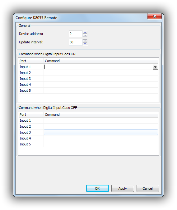
The configuration dialog will look like this:
First, you can set up the device address (corresponds to the jumpers on the board) and the update interval for polling.
Then you can assign a command for each input 1-5, and for the event that the pin goes ON or OFF, respectively.
Scripting
Digital Outputs
To access a K8055 remote from a script, use the following function:
function K8055Remote(iIndex: integer): IK8055Remote;
iIndex is the number of the K8055 remote set up in the system, with 0 being the first (and often) only one.
The function will return a reference to a IK8055Remote interface, which provides amongst others the following methods:
procedure SetDigitalChannel(Channel: integer);
procedure ClearDigitalChannel(Channel: integer);
procedure ClearAllDigital;
A complete call for switching on (setting) digital channel 3 on the first Velleman unit then should look like this:
K8055Remote(0).SetDigitalChannel(3);
Analogue Outputs
The analogue output can be actuated with the following method:
procedure OutputAnalogChannel(Channel, Value: integer);
… where Channel resembles the number of the analogue output (i. e. 1 or 2) and Value is an integer value between 0 and 255:
0leads to a voltage of 0V at the analogue or a duty factor of 0% at the PWM output, respectively.
255leads to a voltage of 5V at the analogue or a duty factor of 100% at the PWM output.
- The effect of values lying in between these extremes can be characterised by:
<Value> / 255 * 5Vor<Value> / 255 * 100%, respectively.
Notably the PWM output can be taken advantage of driving an ON-AIR lamp directly, as long as it meets the voltage and current limits of the transistor used in the circuit (BC337 that is, as of fall 2019).

