Table of Contents
DHD Series 52, RM4200D, RM3200D
This article covers remote control of mAirList with digital broadcast consoles from DHD audio GmbH.
Supported Hardware
The DHD remote control interface in mAirList supports the following consoles from DHD:
- Series 52 (all models: 52/MX, 52/RX, 52/SX, 52/DX, 52/TX, RX2, SX2)
- RM4200D
- RM3200D
For the RM2200D, see here.
Configuration
To add a new remote control interface, open either the standalone configuration program (mAirListConfig, from the Windows Start Menu), or open the mAirList Control Panel from the menu next to mAirList button in the playout window toolbar, then go to Remote Control, click Add and select DHD 52/RM4200D/RM3200D.
The DHD remote control configuration dialog will appear.
General
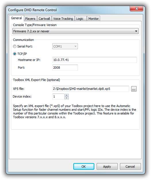
On the General tab, you configure the type of your DHD console, and the way mAirList should communicate with it.
Console Type
Please select your console type and/or firmware version here. Some consoles, in particular the RM3200D, use a slightly different protocol, so we need to give mAirList a hint here which model we're using.
Communication
Please select whether you are using a serial or network connection to your console.
Newer models (including all Series 52 consoles, and also the RM4200D with a recent DSP core) support remote control via TCP/IP, which is generally the preferred method. The IP address can be retrieved from the Maintenance Window in the DHD Toolbox. The TCP port is generally 2008.
Serial communication is the only method supported by the RM3200D. Please select the port here, and don't forget to set up the COM parameters (baudrate etc.) under mAirListConfig → Misc. → Serial Ports as well: 38400, 8N1.
Toolbox XML Export File (optional)
For easy setup, you can export the DHD configuration from the DHD Toolbox as an XML file (*.xp5). Use Project → Export → Save Project as XML in the DHD Toolbox application, then select the file here in the mAirList configuration dialog. If you have more than one device (core) in the Toolbox project, specify the index of the associated device (same order as in the Toolbox project).
Linking the XP5 file with mAirList has two benefits:
- You can use the “Automatic Setup” function (see below) to conveniently fill out Fader Channel and Logic fields.
- You will be able to use the DHD Console window in the playout application.
Note: The XP5 XML format is not documented and not officially supported by DHD. We did our best to parse the file and extract all relevant information. But future Toolbox versions may change the format of the XP5 files without notice. If your XP5 file fails to load, in particular after an update of the DHD Toolbox application, please contact mAirList support so we can adjust our code to the new format.
The XP5 export function is only available in Toolbox 7 and 8.
Starting with mAirList 6.2.3, the XP5 file is only used for the DHD Console window. Automatic configuration of fader channels and logics is done using the Extended Audio and Logic ID export from Toolbox (see next paragraph). From that version, mAirList configuration is compatible with Toolbox 9.
Toolbox Import (mAirList 6.2.3 and up)
mAirList can import Audio ID, Logic ID and Fader Channel information from Toolbox 7.x, 8.x or 9.x. This will allow a more convenient setup of the player etc. configuration, as you don't have to type the fader channel numbers and logic IDs manually anymore, but you can just select them from the list.
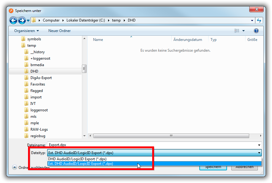
In order to use this function, you just first export the IDs as an “Ext. DHD AudioID/LogicID Export (*.dpx)” file from DHD Toolbox (Project → Export → Export AudioIDs/LogicIDs). Make sure that you select the correct file type with the “Ext.” in it, as the ordinary export will be missing the fader channel numbers:
The resulting *.dpx file can then be imported into the mAirList configuration. If you have more than one device in your Toolbox project, or more than one virtual mixer in your core, you will be prompted to select the device/mixer from the list.
The IDs are copied into the mAirList configuration. It is not necessary to keep the *.dpx file after import.
Players
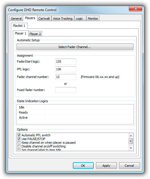
On the Players tab, we specify the parameters for the (bi-directional) faderstart.
You must fill out the following fields:
- FaderStart logic (for faderstart console → mAirList)
- PFL logic (for PFL switching, bidirectional)
- Fader channel number or fixed fader number (for faderstart mAirList → console)
If imported Toolbox data on the Toolbox Import tab (or linked an XP5 file in the case of a mAirList ersion older than 6.2.3), click the Select Fader Channel button and select the channel that is associated with this player.
Without Toolbox import data, you must look up the Fader Channel and Logic values manually:
The FaderStart logic and PFL logic addresses are used to control the mAirList player from the console, i.e., to start the player when the channel is opened on the console, and to start PFL playback when you press the PFL/CUE button on the channel strip.
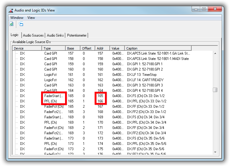
For newer consoles configured through the Toolbox 5 software, you can look up these values in the Available Audio/Logic IDs window, found in the View menu of Toolbox5. Scroll down to the FaderStart (Ch) and PFL (Ch) lines of the associated input, and read the values in the Addr column. The value for PFL is most likely the one for FaderStart + 1, in our example 165 and 166:
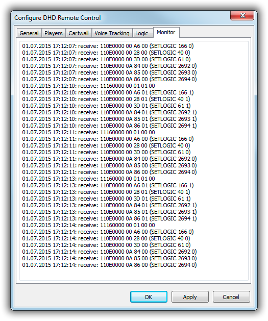
For older consoles like the RM3200D, please refer to the manual, or use the Monitor feature to find out the relevant logic addresses (see below).
To control the console from the mAirList players – open the fader when you click PLAY with the mouse, or activate PFL when you click PFL – mAirList needs to know either the Fader Channel number or Fixed fader number of the associated input.
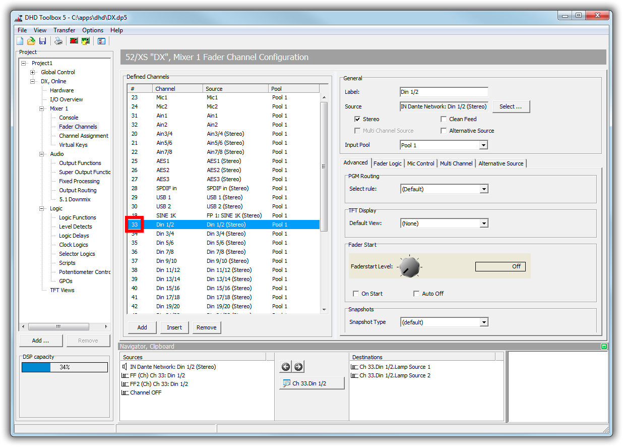
Using the Fader Channel number is generally the preferred method, as it will work regardless of the actual fader that the input is assigned to. You can look up the Fader Channel number on the Fader Channels page in Toolbox 5:
Fader Channels require at least Firmware 6.x.x.x. On older consoles like the RM3200D (but optionally also on more recent consoles) you use fixed fader numbers instead, specifying the number of the fader that the input is assigned to.
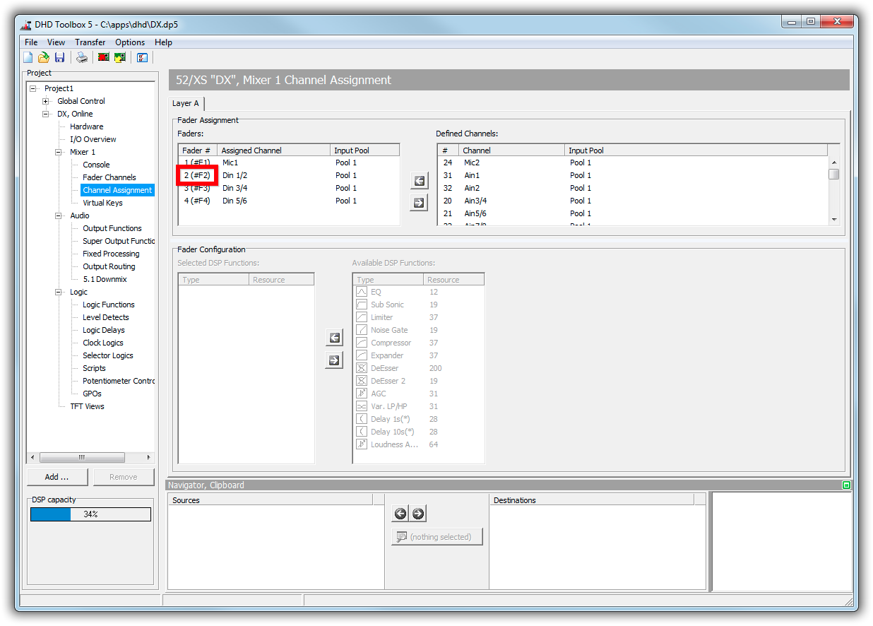
The fader numbers can be looked up on the Channel Assignment page in Toolbox 5:
If you use Virtual Mixers, Virtual Mixer 1 is assumed unless you add one of the following values to the fader number in order to address a fader on a virtual mixer:
- 256: Virtual Mixer 2
- 512: Virtual Mixer 3
- 768: Virtual Mixer 4
In the State Indication Logics section, you can enter Logic IDs that mAirList will set to ON when the player is in a particular state (idle, ready, active).
At the bottom of Players tab, there are a couple of options:
- Automatic PFL switch: When enabled, mAirList will switch the PFL function of the fader on when you start PFL playback. You can disable this option if you use a separate PFL sound card.
- Use PAUSE/STOP: When enabled, mAirList will send a
PLAYER x-y PAUSE/STOPcommand to the player when the channel is closed, otherwise aPLAYER x-y STOPcommand. - Keep channel on when player is paused: When enabled, the channel switch will remain in ON position when you pause the player, e.g. by pulling the fader down to the bottom. Otherwise, the channel will immediately go to OFF.
- Disable channel on/off switching: Normally mAirList will switch on/off the channel when the player is started or stopped; this behavior can be disabled here.
- Enable motorized fader control: Check this if you are using a DHD model with motorized faders (e.g. SX2 or RX2) and the “Channel Start ON/OFF” function in Toolbox (rather than “Channel ON/OFF”). mAirList will move the faders to 0 dB or off, respectively, as you start or stop a player from the GUI. You should also check Disable channel on/off switching (see above) as motorized channels do not use the on/off function.
- Set channel label to item title: When enabled, the title of the item loaded into the player will be sent to the console, where it will be displayed on the channel strip OLED.
Cartwall
On the Cartwall tab, you will find the settings for the cartwall fader, and the individual cart players.
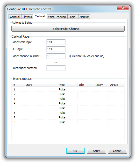
Cartwall Fader
Usually, all cart players will use the same audio output (and thus input channel on your mixer). The cartwall state (ON AIR, OFF AIR, PFL) can be linked to the state of the associated fader on your console, so the cartwall follows the fader start, and vice versa.
Specify the FaderStart logic, PFL logic, and Fader Channel or fixed fader number; or use the Automatic Setup function if you imported Toolbox data. Please refer to the Players section above for an explanation of these parameters.
Player Logic IDs
Most DHD consoles have some general purpose (GP) buttons that you can use to control the cart players. The cartwall can start/stop players as you press the button, and it can also report the state of the individual cart players (idle/emtpy, ready, active) by sending logic state changes to the console.
In the Start column, enter the the logic address of the button (or GPI) that you use to start/stop this cart player. This can be looked up in the Available Audio/Logic IDs dialog in Toolbox 5 (see above).
The start logic can either be Pulse (mAirList will issue a CARTWALL x CLICK command when the logic goes from off to on) or Tally (CARTWALL x START when logic goes on, CARTWALL x STOP when logic goes off). For the push buttons on the DHD console, you would probably use Pulse.
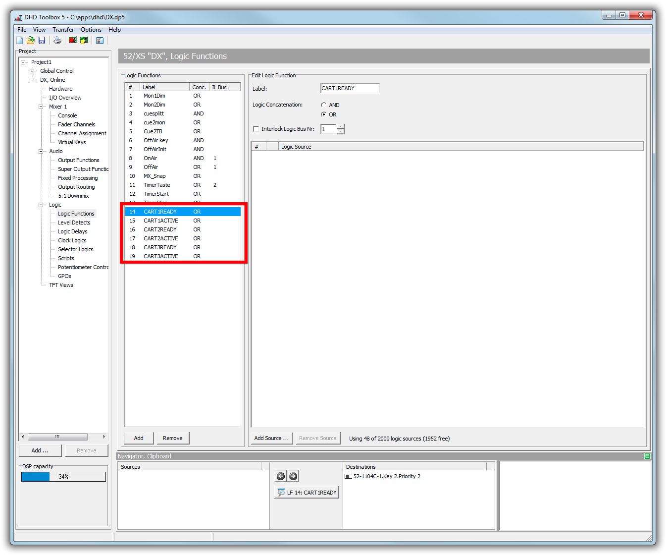
Implementing visual feedback of the cart player state involves a bit of preparatory work in Toolbox 5. First, we have to define two logic functions for each cart player, one for “ready” and one for “active”. Name them e.g. CART1READY and CART1ACTIVE:
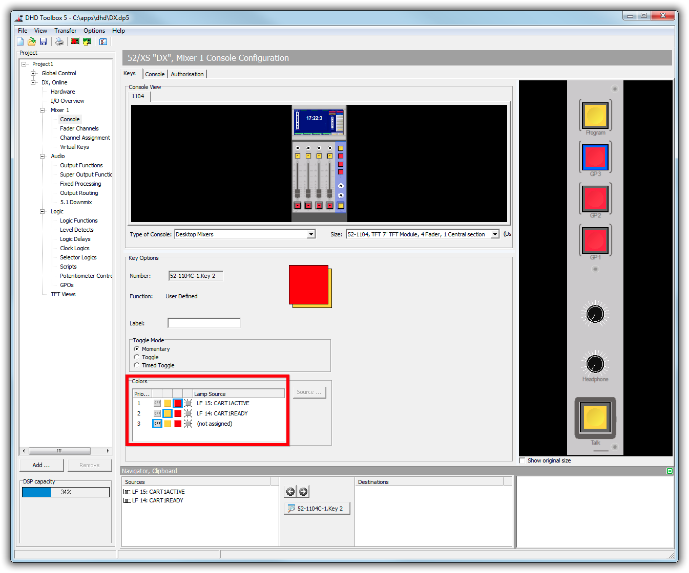
Then go to the configuration of the associated key, choose two colors, and assign the logic functions accordingly:
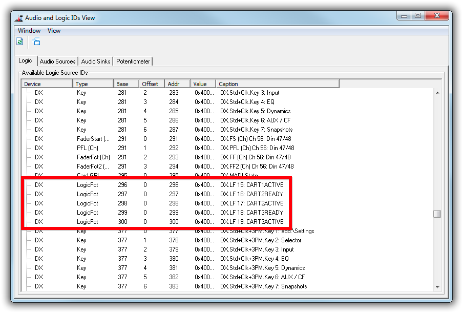
Finally, look up the logic addresses of our logic functions in the Available Audio/Logic IDs dialog:
Then enter these addresses into the Ready and Idle columns of the associated cart player.
Options
The options Disable channel on/off switching and Enable motorized fader control have the same meaning as with the players (see above).
Voice Tracking
With the Voice Tracking bindings, you can accomplish three things:
- Start the Player A and Player B output in the Voice Track recorder when you open the associated faders on your console.
- Start the recording when you open the MIC fader on the console.
- Record the fader movements of Player A and Player B, and transform them into a volume envelope in the resulting recording.
For the volume envelope function, firmware 7.x.x.x or higher is required.
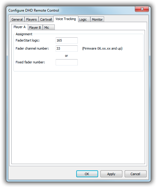
You have to specify the FaderStart logic (PFL is not required) and Fader Channel number or Fixed fader number. See the Players section above for the meaning of these parameters.
Logic
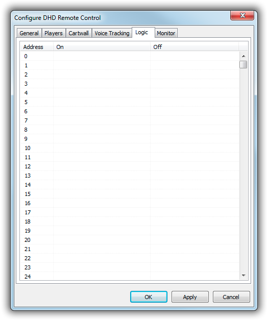
On the Logic tab, you can assign any logic address and state change (on/off) a remote control command:
Monitor
The Monitor tab is only available/active when the configuration was called from the mAirList Control Panel in the playout main window, not from the standalone configuration program (mAirListConfig!).
DHD Console
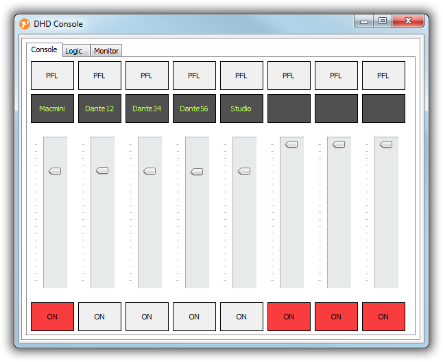
The DHD Console provides manual remote control of your DHD mixer from the mAirList playout application. It is located in the menu next to the mAirList button in the main toolbar. The DHD remote must be active and an XP5 file must be linked in order to use the DHD Console.
Console
On the first tabs, you see a representation of the fader strips of your console, each with a PFL button, channel label, volume slider, and ON/OFF button.
Right-click the channel label to select another input channel for that fader.
The controls are fully bi-directional, so you can control the physical console from this window, and changes made on the phyiscal console are also reflected in the window.
Logic
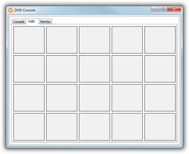
The Logic tab provides 20 buttons that can be used to control logic states in your DHD console.
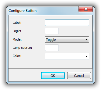
Right-click a button to adjust its properties:
Set the label, the logic ID (as found in the Toolbox project) and the mode (toggle, tally or inverse tally). The buttons can also indicate logic states by changing their color. To use this function, enter a logic ID to be used as the lamp source, and select a color.
Monitor
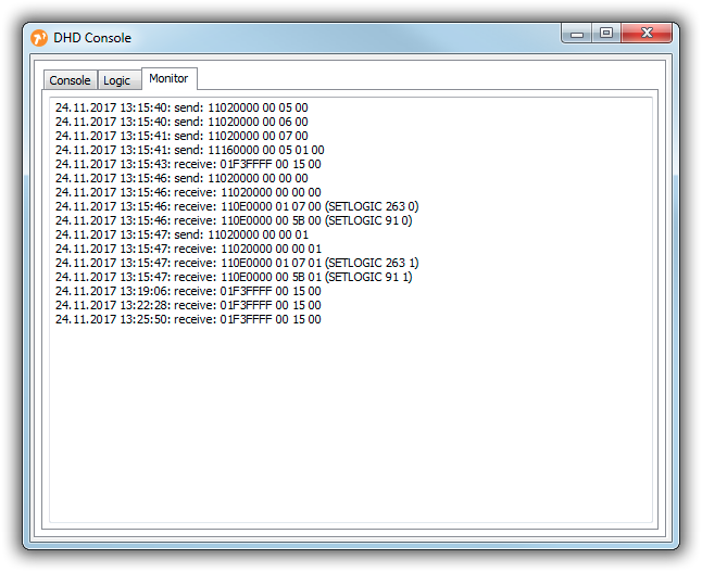
The third tab shows a list of messages sent to and received from the DHD core, for debugging purposes, similar to the Monitor tab of the remote control configuration when opened through mAirList Control Panel.
Actions
The DHD interface provides a couple of actions that can e.g. be used in the Event Scheduler. You can find them in the DHD submenu of the list of available actions when you click Add in the action list editor.
Set PFL
This action will switch the PFL function of a fader (or Fader Channel) on or off. Specify either a Fader Channel or a fixed fader number.
Set all PFL off
This action will turn PFL off for all faders.
Set Fader On/Off
This action will turn on or off a fader (addressed by fixed fader number or Fader Channel).
Set Logic
Using this action, you can set logic addresses to on or off.
Scripting
The DHD interface can be accessed via DHDRemote(0) (or DHDRemote(1) etc. if you have more than one DHD remote controls registered). The function will return a IDHDRemote interface, which has, amongst others, the following methods:
  procedure SetMonitorChannel(iNumber: byte; iLeft, iRight: word);
  procedure SetPFL(iChannel: word; iValue, iAutoMute: boolean);
  procedure SetAllPFLOff;
  procedure SetFaderOn(iChannel: word; iValue: boolean);
  procedure SetLogic(iAddress: word; iValue: boolean);
  procedure RequestLogic(iAddress: word);
  procedure SetChannelInputNumber(iFader, iChannel: word);
  procedure SetOutputRouting(iOutput, iInput: cardinal);
  procedure SetChannelDisplay(iChannel: word; iText: string);
  procedure ResetChannelDisplay(iChannel: word);
These functions match the messages with the same names in the DHD External Control Protocol. Please note that the raw parameters must be specified for all channel parameters, in particular fader numbering starts at 0 (= Fader 1).
To send messages with are not implemented by the above methods, you can use one of the following two functions:
  procedure SendPacket(iID: cardinal; iData: AnsiString);
  procedure SendPacketRaw(iID: cardinal; iLength: integer = 0;
    iData0: byte = 0; iData1: byte = 0; iData2: byte = 0;
    iData3: byte = 0; iData4: byte = 0; iData5: byte = 0;
    iData6: byte = 0; iData7: byte = 0);
In background scripts, you can use the following procedure to process raw packets received by any DHD remote:
procedure OnDHDCommand(Remote: IDHDRemote; ID: cardinal; Len: integer;
  Data0, Data1, Data2, Data3, Data4, Data5, Data6, Data7: byte);
begin
end;
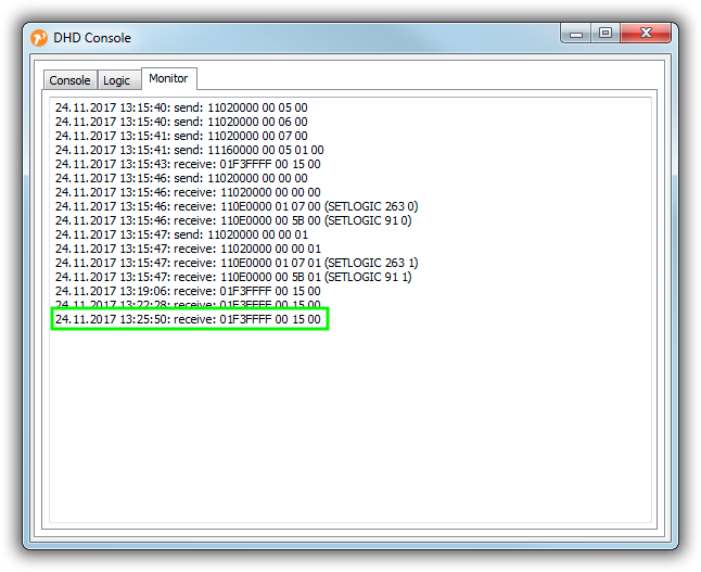
Remoterepresents the ID of the respective DHD device,IDrepresents the LogicID of the respective DHD control in hexadecimal numbers,Lenrepresents the number of data bytes received, andData<n>represent the individual data bytes sent.
So in this example …
… a query for the highlighted data packet might look like this:
procedure OnDHDCommand(Remote: IDHDRemote; ID: cardinal; Len: integer;
  Data0, Data1, Data2, Data3, Data4, Data5, Data6, Data7: byte);
begin
  if (ID = $01F3FFFF) AND (Data0 = 0) AND (Data1 = 15) AND (Data2 = 0) then begin
    // do something
  end;
end;
